MoveIt Setup Assistant
Overview
The MoveIt Setup Assistant is a graphical user interface for configuring any robot for use with MoveIt. Its primary function is generating a Semantic Robot Description Format (SRDF) file for your robot, which specifies additional information required by MoveIt such as planning groups, end effectors, and various kinematic parameters. Additionally, it generates other necessary configuration files for use with the MoveIt pipeline. To use the MoveIt Setup Assistant, you will need to have a URDF file for your robot.
Once you have a URDF file, you can open the MoveIt Setup Assistant and import your URDF. This tutorial will guide you through a series of steps to configure various aspects of your robot, such as defining its kinematic structure, specifying planning groups and end effectors, and collision checking related settings. To learn more about the URDF and SRDF, you can refer to the URDF and SRDF Overview page.
Getting Started
MoveIt and ROS 2
Follow the instructions for installing MoveIt first if you have not already done that.
We use the moveit_resources_panda_description package. This package should already be included in your workspace if you’ve completed the MoveIt installation instructions.
Step 1: Start
To start the MoveIt Setup Assistant:
ros2 launch moveit_setup_assistant setup_assistant.launch.py
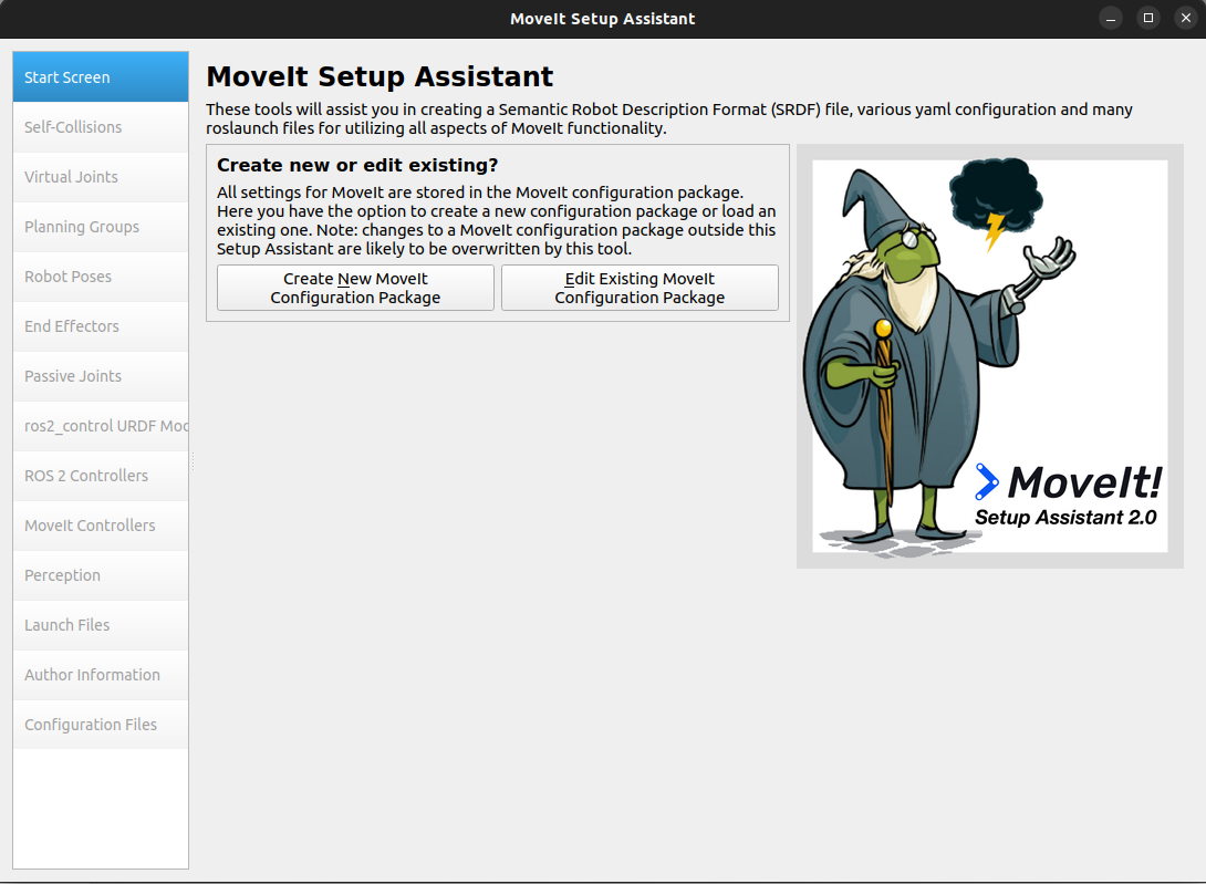
This will bring up the start screen with two choices: Create New MoveIt Configuration Package or Edit Existing MoveIt Configuration Package.
Click on the Create New MoveIt Configuration Package button to bring up the following screen:
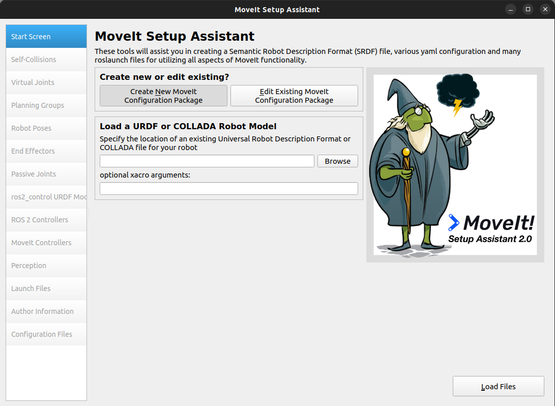
Click on the Browse button and navigate to the
panda.urdffile from themoveit_resources_panda_description packageavailable in the following path:~/ws_moveit2/src/moveit_resources/panda_description/urdf/panda.urdf
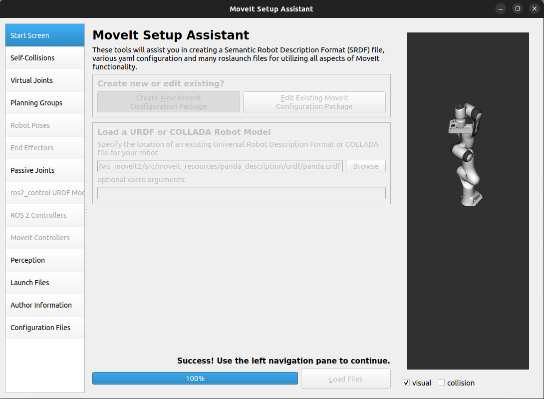
Choose that file and then click Load Files. The Setup Assistant will load the files (this might take a few seconds) and present you with this screen:
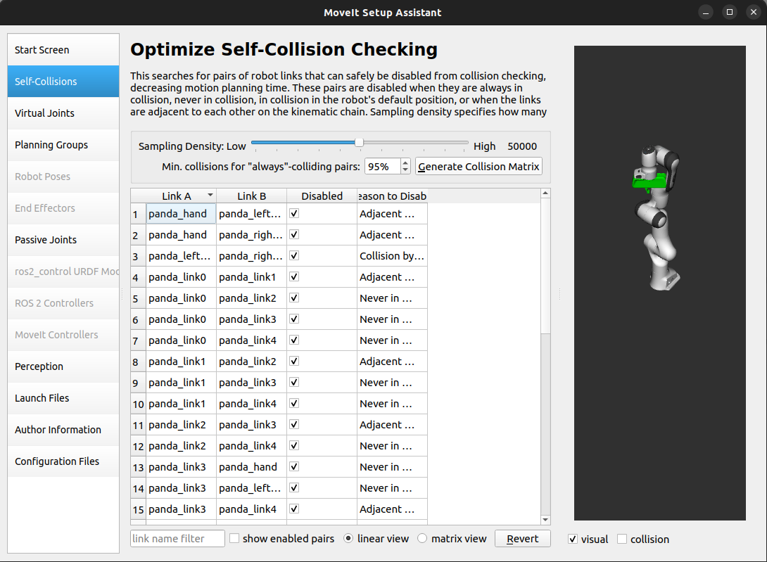
Step 2: Generate Self-Collision Matrix
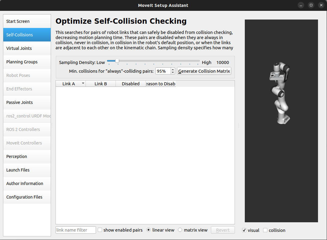
The default Self-Collision matrix generator can help reduce motion planning time by disabling collision checking for pairs of links on the robot that are known to be safe. This is achieved by determining which pairs of links are always in collision, never in collision, in collision in the robot’s default position, or adjacent to each other on the kinematic chain.
You can set the sampling density, which determines how many random robot positions are checked for self-collision. Although the generator checks 10,000 random positions by default, using maximum values for sampling density is recommended to ensure more accurate results. The collision checking is done in parallel to reduce the overall processing time for generating the collision matrix.
To generate the collision matrix, select the Self-Collisions pane on the left-hand side of the MoveIt Setup Assistant and adjust the self-collision sampling density. Then, click on the Generate Collision Matrix button to initiate the computation. The Setup Assistant will take a few seconds to compute the self-collision matrix, which involves checking for pairs of links that can be safely disabled from collision checking.
Once the computation is complete, the results will be presented in the main table. The table shows the pairs of links that have been identified as either safe or unsafe to disable from collision checking. Links that are safe to disable are marked with a checkmark. You can manually adjust the checkmarks as needed to enable or disable self-collision checking for specific link pairs.
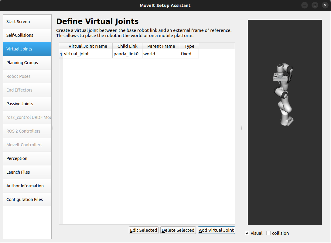
Step 3: Add Virtual Joints
Virtual joints are primarily used to connect robots to the world.
In the case of the Panda arm, which is a fixed base manipulator, defining a fixed virtual joint
is optional. However, we will define a fixed virtual joint that attaches the panda_link0
of the arm to the world frame. This virtual joint signifies that the base of the arm
remains stationary in the world frame.
Click on the Virtual Joints pane selector. Click on Add Virtual Joint.
Set the joint name as
virtual_joint.Set the child link as
panda_link0and the parent frame name asworld.Set the Joint Type as
fixed.Click Save and you should see this screen:
Note
Virtual joints are particularly beneficial for robots with mobile bases, such as mobile manipulators. They enable modeling the motion of the robot’s base, which is essential for motion planning and control. For instance, a virtual planar joint can be used to connect the robot base frame to the odometry frame, effectively representing the robot’s movement in the environment.
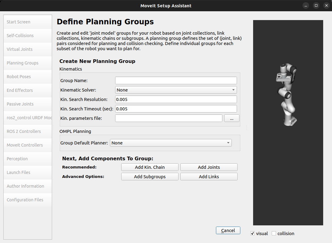
Step 4: Add Planning Groups
Planning groups in MoveIt semantically describe different parts of the robot, such as the arm or end effector, to facilitate motion planning.
A move group can be configured to correspond to a specific kinematic chain on the robot, which is a set of links and joints that define a sequence of transformations from the base of the robot to the end effector. For example, a move group might be defined to represent the arm of a robot, which would consist of all the links and joints necessary to move the arm.
Move groups can also be represented by sets of links or joints corresponding on the robot. For example, a move group might be defined to represent the gripper of a robot, which would consist of all the links or joints necessary to move together to realize a gripper opening or closing motion.
Click on the Planning Groups pane selector.
Click on Add Group and you should see the following screen:
Add the arm group
We will first add Panda arm as a planning group
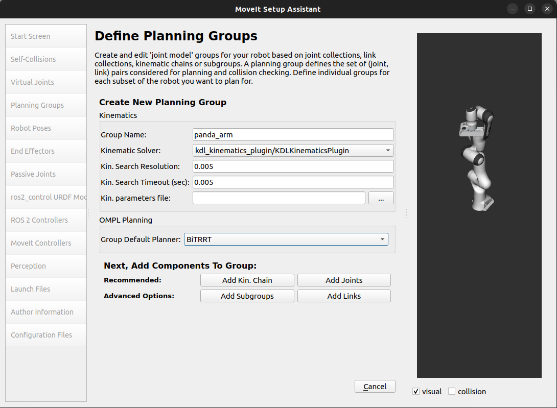
Now, click on the Add Joints button. You will see a list of joints on the left-hand side. You need to choose all the joints that belong to the arm and add them to the right-hand side. The joints are arranged in the order that they are stored in an internal tree structure. This makes it easy to select a serial chain of joints.
Click on
virtual_joint, hold down the Shift button on your keyboard and then click on thepanda_joint8. Now click on the > button to add these joints into the list of Selected Joints on the right.
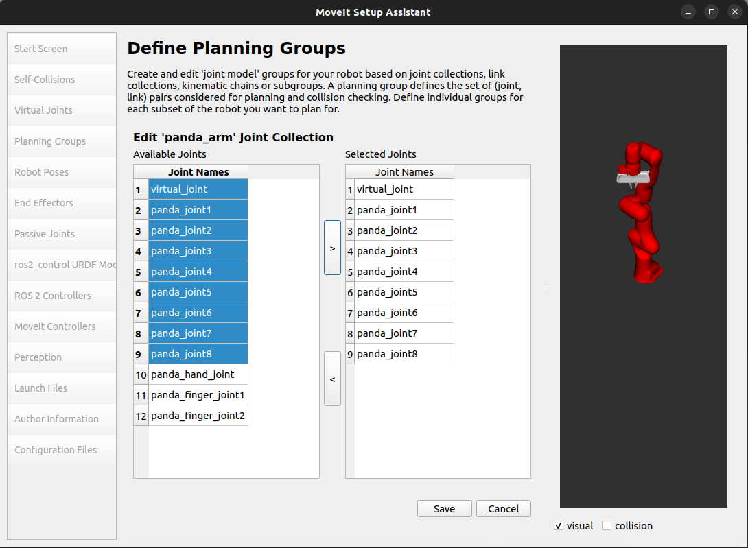
Click Save to save the selected group.
Add the end effector group
Note
The end effector is not made of links attached in a serial chain. Therefore, the group’s Kinematic Solver should be set to None.
Proceed with the following steps.
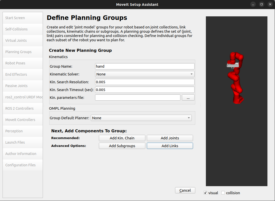
Click on the Add Group button.
Enter Group Name as
hand.Let Kinematic Solver stay at its default value, which is None.
Let Kin. Search Resolution and Kin. Search Timeout stay at their default values.
Click on the Add Links button.
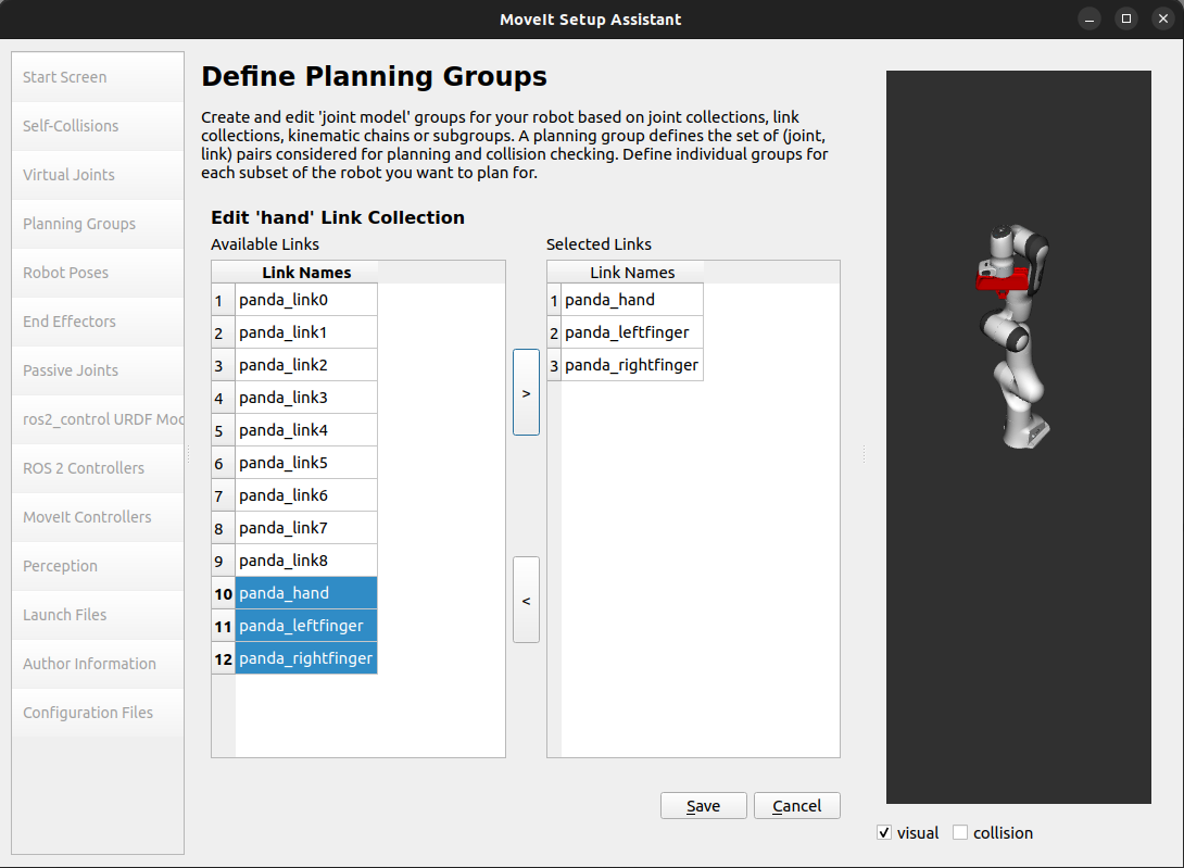
Choose
panda_hand,panda_leftfinger, andpanda_rightfingerand add them to the list of Selected Links on the right-hand side.Click Save.
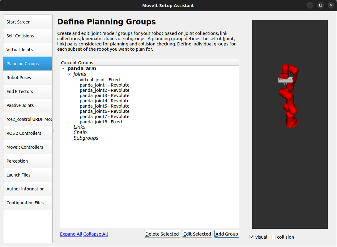
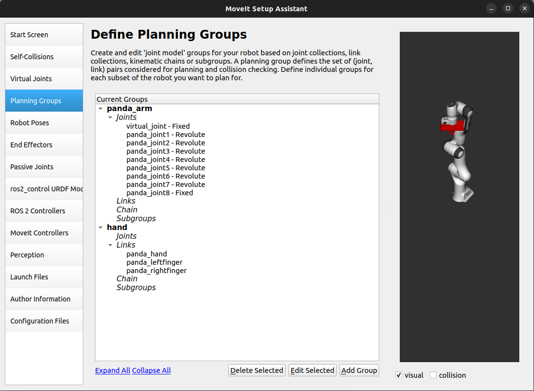
After both arm and hand groups are added, the custom groups list should look as follows.
Note
It is possible to build move groups composed of other move groups with the Add Subgroup option. This can be beneficial in cases where multiple move groups need to be controlled together, such as when planning for simultaneous motions of multi-arm systems.
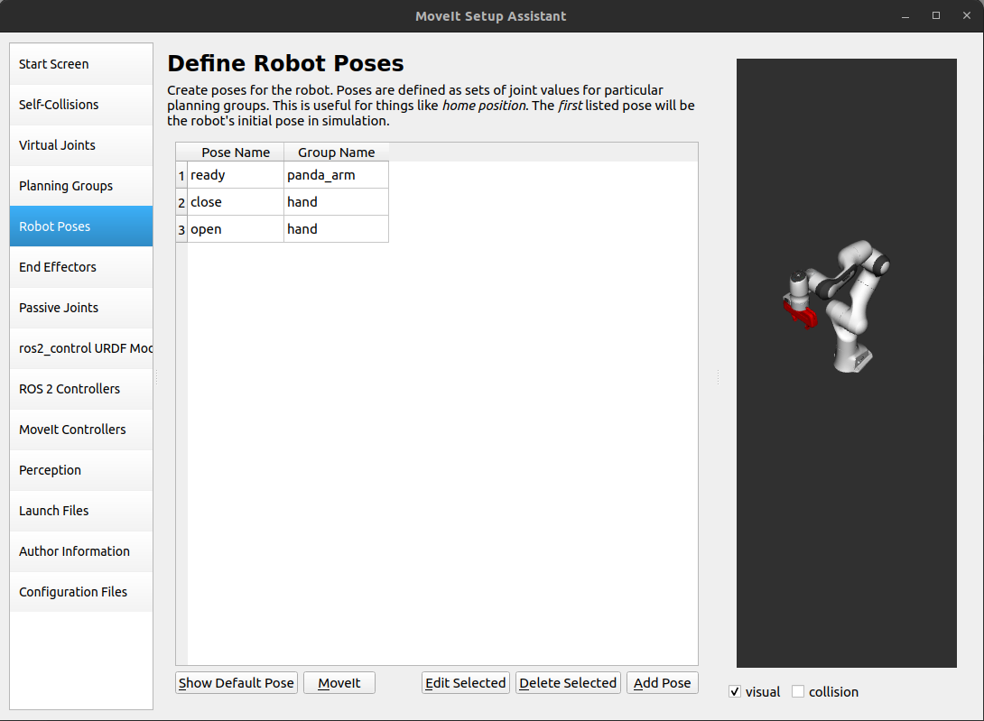
Step 5: Add Robot Poses
The Setup Assistant allows you to add predefined poses to the robot’s configuration, which can be useful for defining specific initial or ready poses. Later, the robot can be commanded to move to these poses using the MoveIt API.
Add ready pose for the arm
Click on the Robot Poses pane.
Click Add Pose. Choose a name for the pose. The robot will be in the default pose, with all joints set to their zero values. Move the individual joints around until you are happy and then Save the pose. Note how poses are associated with particular groups. You can save individual poses for each group.
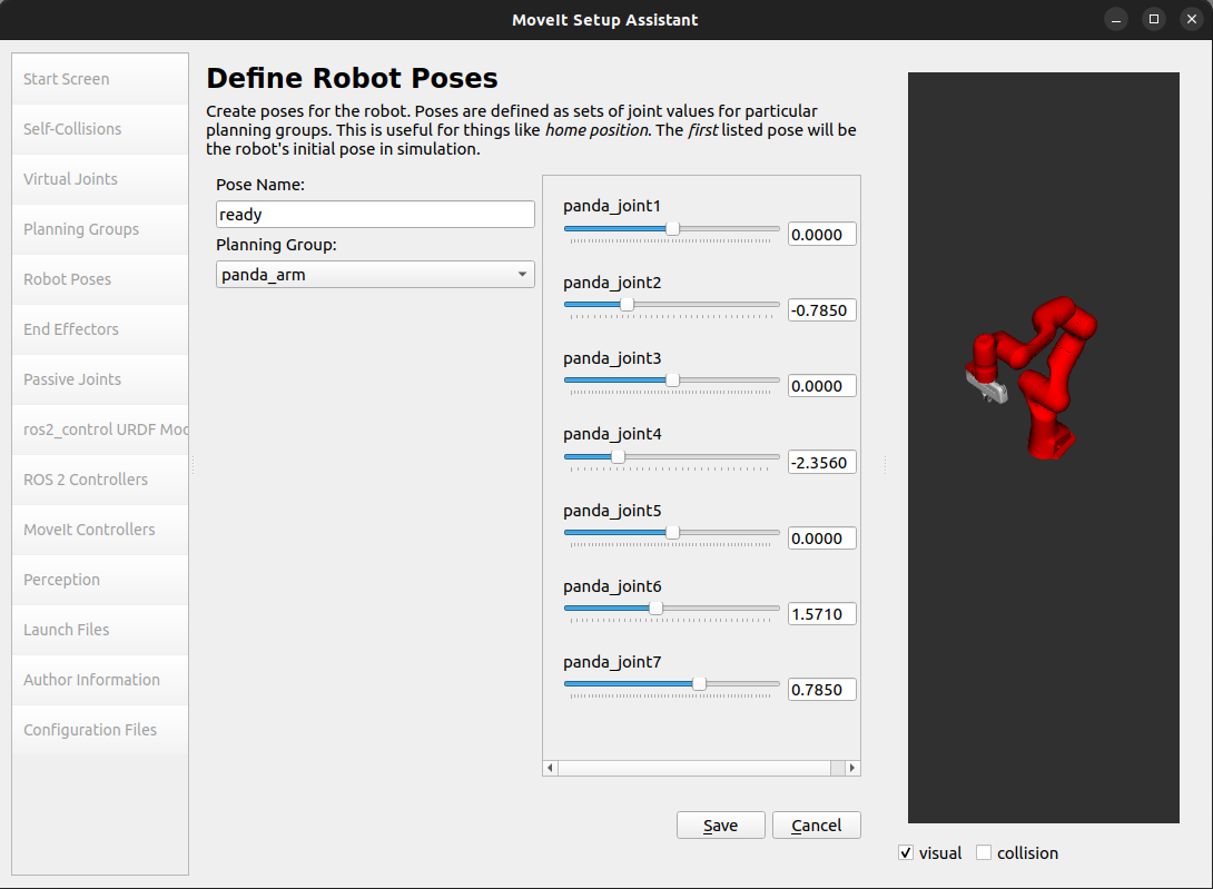
Select the
panda_armand define areadypose for it with the following joint values{0.0, -0.785, 0.0, -2.356, 0.0, 1.571, 0.785}.IMPORTANT TIP: Try to move all the joints around. If there is something wrong with the joint limits in your URDF, you should be able to see it immediately here.
Add open and close poses for the gripper
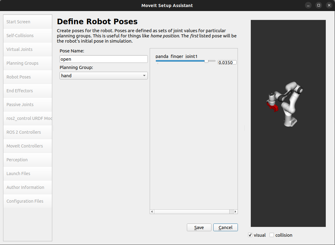
Follow the same steps for defining a pose for the arm, but select the
handgroup.Add an
openpose for thehandgroup with joint value0.035.
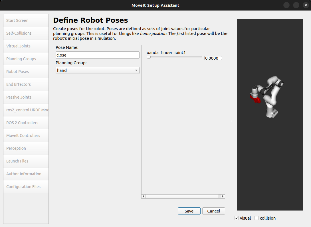
Add a
closepose for thehandgroup with joint value0.0.
Note
Only panda_finger_joint1 appears in the list as panda_finger_joint2 mimics its values.
After the previous steps, the following set of robot poses should be defined for the panda_arm and hand groups.
Step 6: Label End Effectors
Now that we have added the hand of the Panda as a move group, we can designate it as an end effector. By designating a group as an end effector, MoveIt can perform certain special operations on it. For example, end effectors can be used for attaching objects to the arm while carrying out pick-and-place tasks.
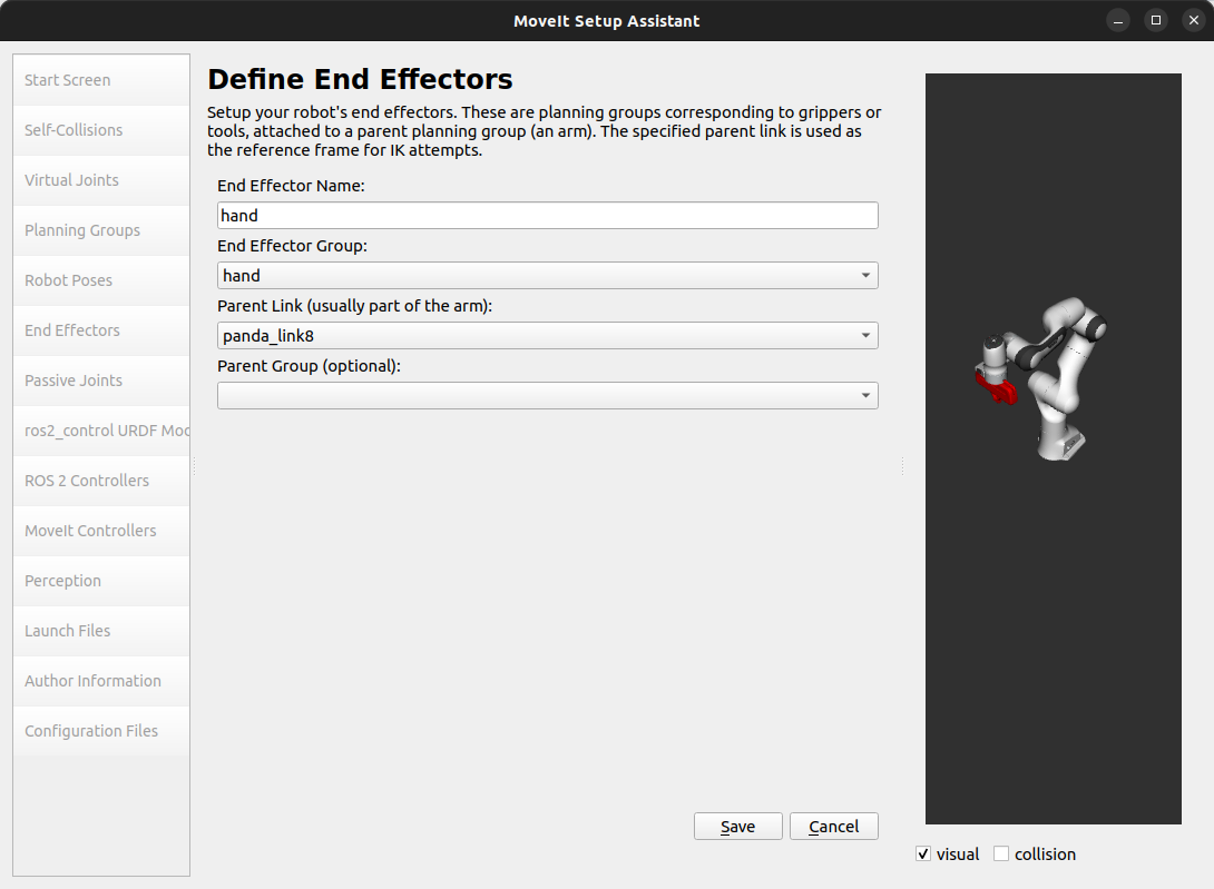
Click on the End Effectors pane.
Click Add End Effector.
Choose
handas the End Effector Name for the gripper.Select
handas the End Effector Group.Select
panda_link8as the Parent Link for this end-effector.Leave Parent Group blank.
Step 7: Add Passive Joints
The Passive Joints pane is meant to allow specification of any passive joints that might exist in a robot. These are joints that are unactuated, meaning that they cannot be directly controlled. It’s important to specify passive joints so that the planners are aware of their existence and can avoid planning for them. If the planners do not know about the passive joints, they might try to plan trajectories that involve moving the passive joints, which would result in invalid plans. The Panda robot arm does not have any passive joints so we will skip this step.
Step 8: ros2_control URDF Modification
The ros2_control URDF Modification pane helps modify the robot URDF to work with ros2_control.
Note
If your robot’s URDF/xacro already includes a ros2_control.xacro, you can skip this step.
This modification adds tags for command and state interfaces for each joint in the defined move groups.
The command_interface tags define the types of commands that can be sent to control the joint.
The state_interface tags define the types of state information that can be read from the joint.
By default the MoveIt Setup Assistant assumes position command interface and position and velocity state interfaces, and we will proceed with this setting.
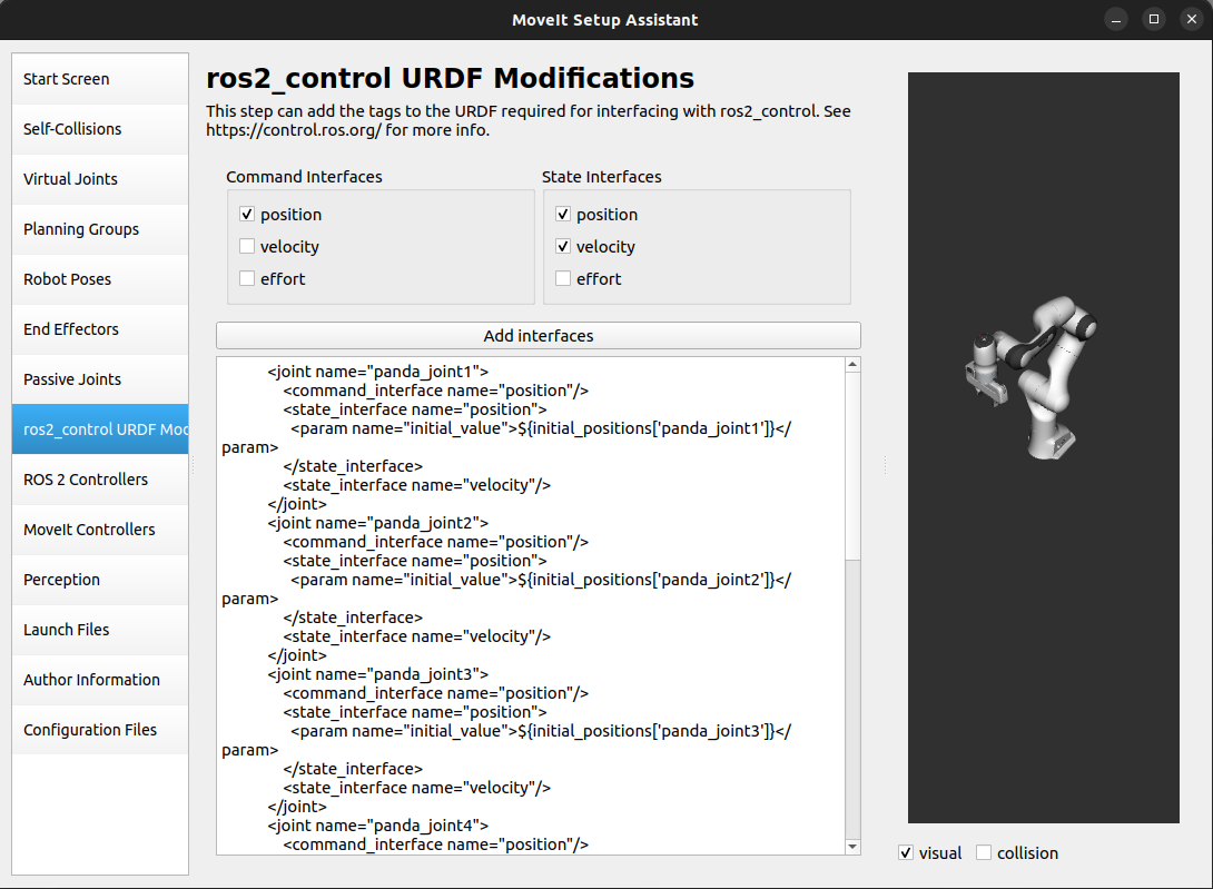
If necessary, select the desired command or state interfaces for your robot joints and then click the Add Interfaces button.
Step 9: ROS 2 Controllers
ROS 2 Control is a framework for real-time control of robots, designed to manage and simplify the integration of new robot hardware. For more details, please look at ros2_control documentation.
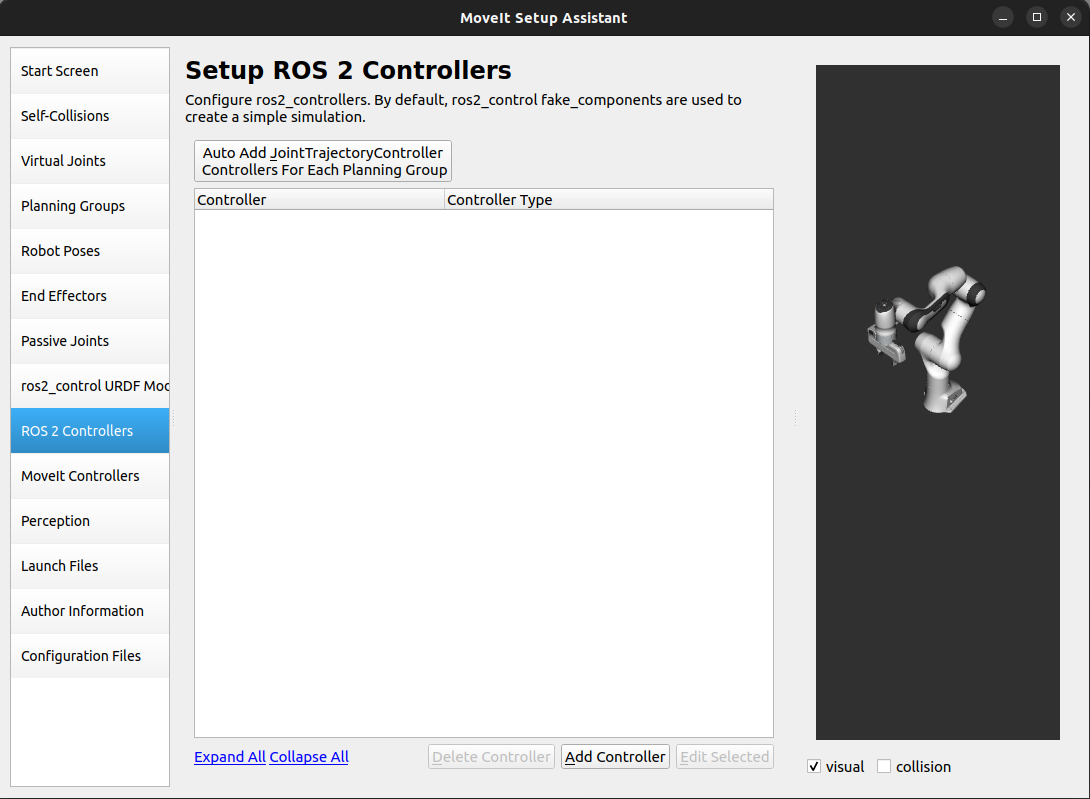
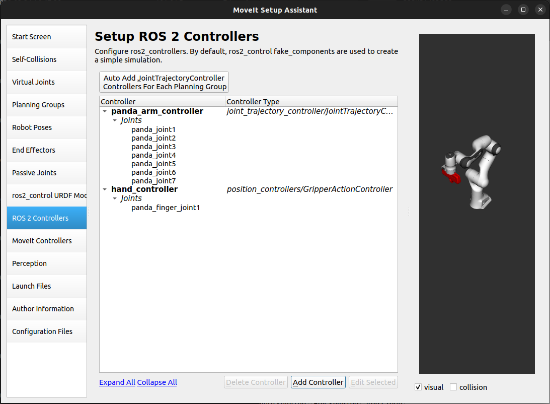
ROS 2 Controllers pane can be used to auto generate simulated controllers to actuate the robot joints.
Add the arm controllers
Click on the ROS 2 Controllers pane selector.
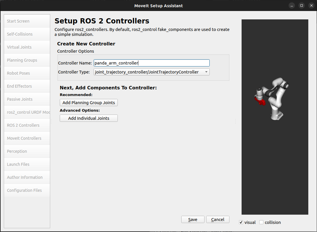
Click on Add Controller and you should see the following screen:
We will first add Panda arm joint trajectory controller.
Enter Controller Name as
panda_arm_controller.Choose joint_trajectory_controller/JointTrajectoryController as the controller type
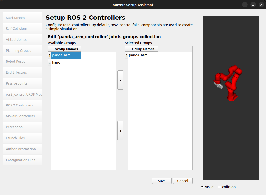
Next, we need to choose the controller joints. Joints can be added individually or by move group.
Now, click on Add Planning Group Joints.
Choose the
panda_armgroup from the Available Groups tab and add it to the Selected Groups.Click Save to save the selected controller.
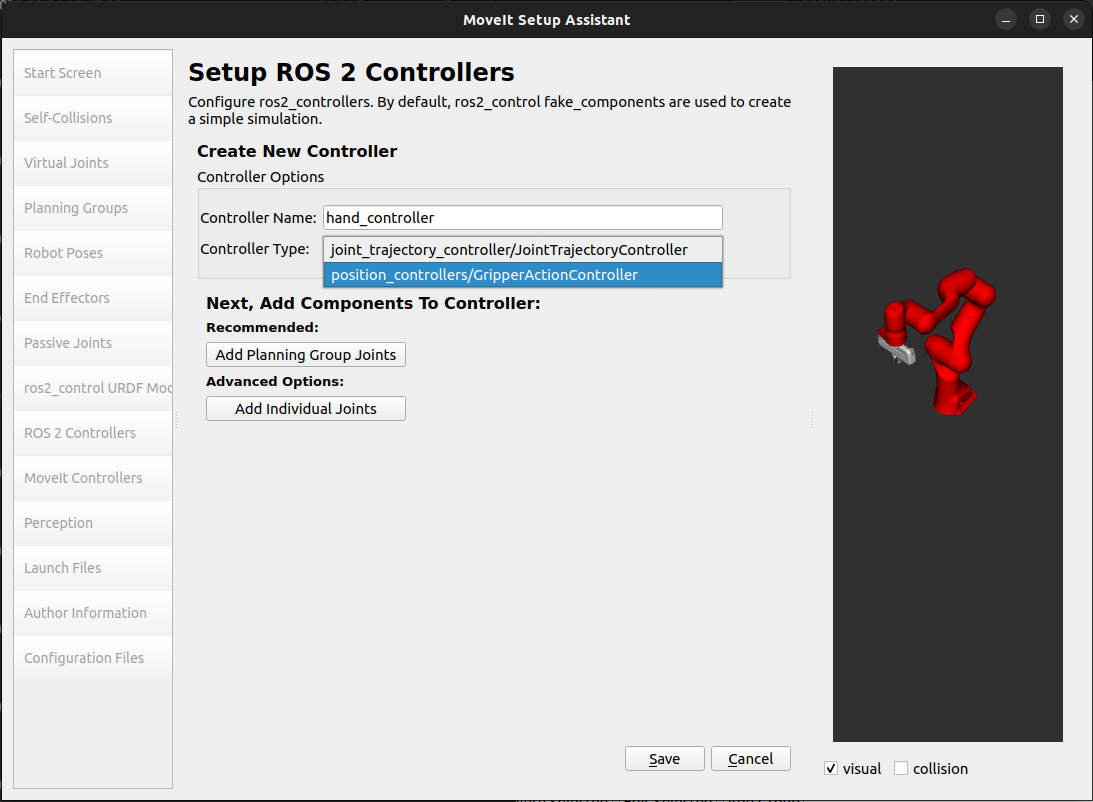
Add the hand controllers
Follow the same steps for the arm, but choose position_controllers/GripperActionController
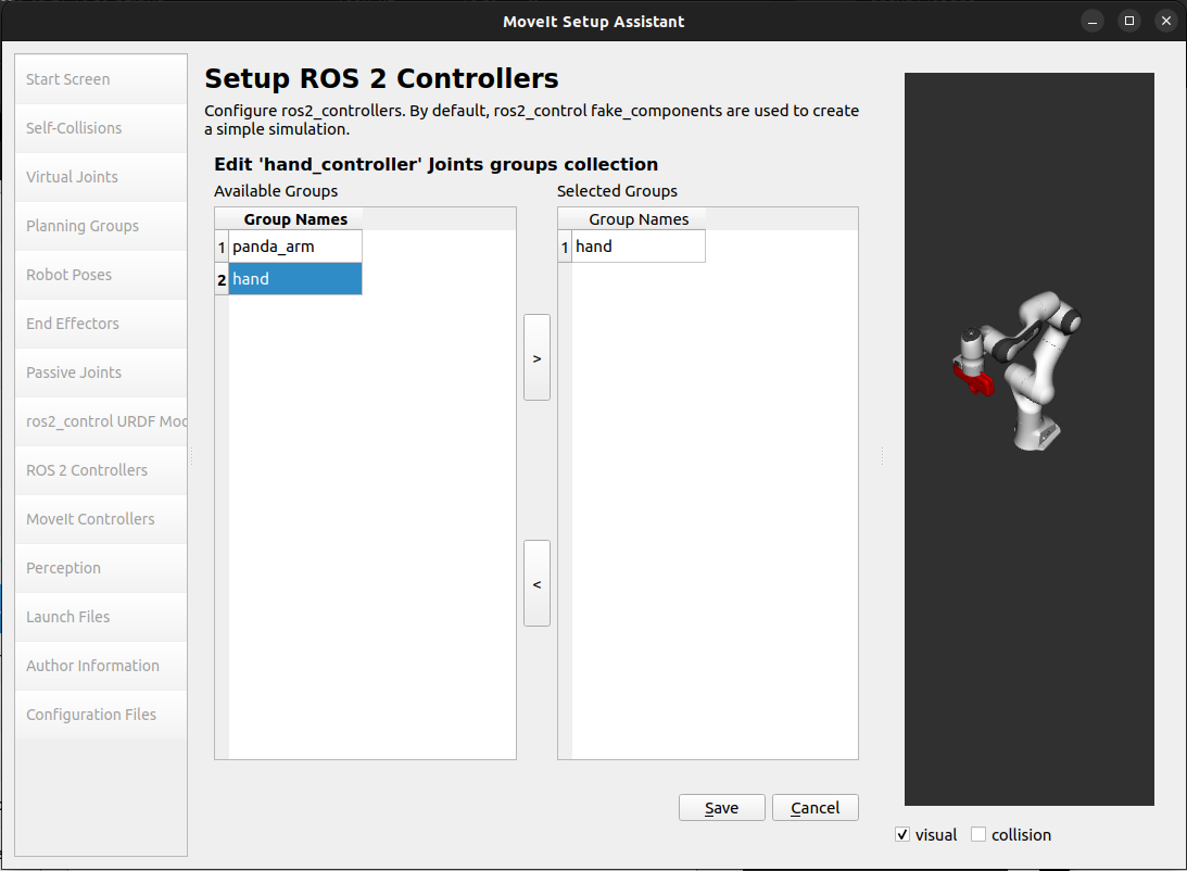
Choose
handgroup from the Available Groups tab and add it to the Selected Groups.Click Save to save the selected controller.
After selecting the arm and hand controllers, the controllers list should be as follows.
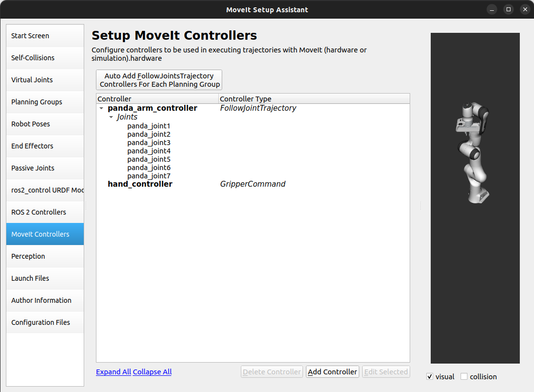
Step 10: MoveIt Controllers
MoveIt requires trajectory controllers with a FollowJointTrajectoryAction interface for
executing planned trajectories. This interface sends the generated trajectory to the robot ROS 2 Controllers.
The MoveIt Controllers pane can be used to auto-generate the controllers to be used by the MoveIt controller manager. Ensure that the controller names match those configured in the previous ROS 2 controller step. The user interface for this step is similar to the previous one.
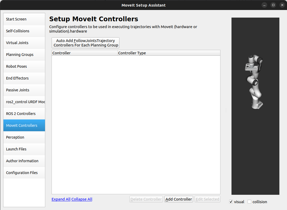
Add the arm MoveIt controllers
Click on the MoveIt Controllers pane selector.
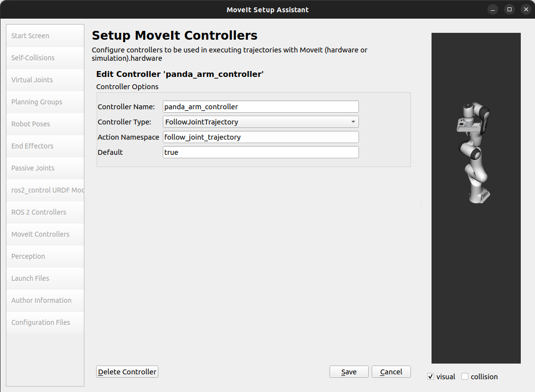
Click on Add Controller to create a new arm controller.
Enter Controller Name as
panda_arm_controller.Choose FollowJointTrajectory Controller Type.
Choose the controller joints with the
panda_armplanning group.Save the controller.
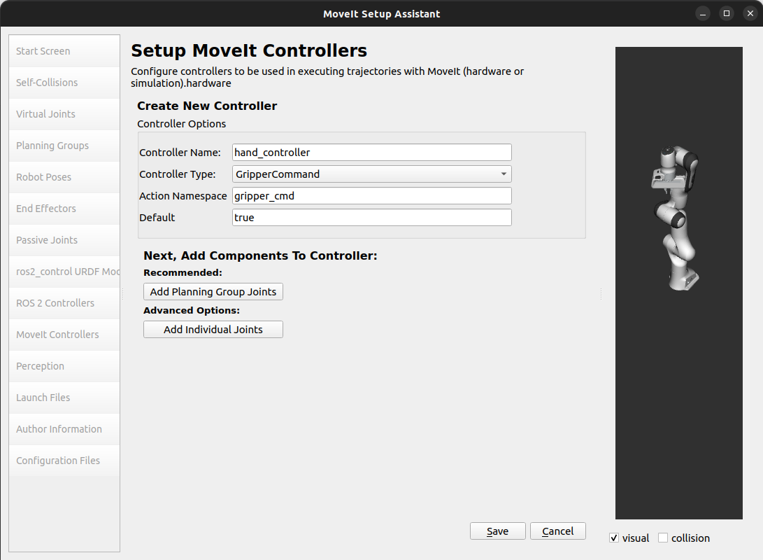
Add the hand MoveIt controllers
Click on Add Controller to create a new controller.
Enter Controller Name as
hand_controller.Choose Gripper Command Controller Type.
Choose the controller joints with the
handplanning group.Save the controller.
After completing the previous steps, the MoveIt Controllers list for the arm and hand should appear as follows.
Step 11: Perception
The Perception tab in the Setup Assistant is used to configure the settings for 3D sensors used by the robot. These settings are saved in a YAML configuration file named sensors_3d.yaml.
In case of sensors_3d.yaml was not needed, choose None and proceed to the next step.

To generate point_cloud configuration parameters, see the following example:
Note
This configuration is not valid for the Panda robot arm because it does not have a head_mounted_kinect camera.
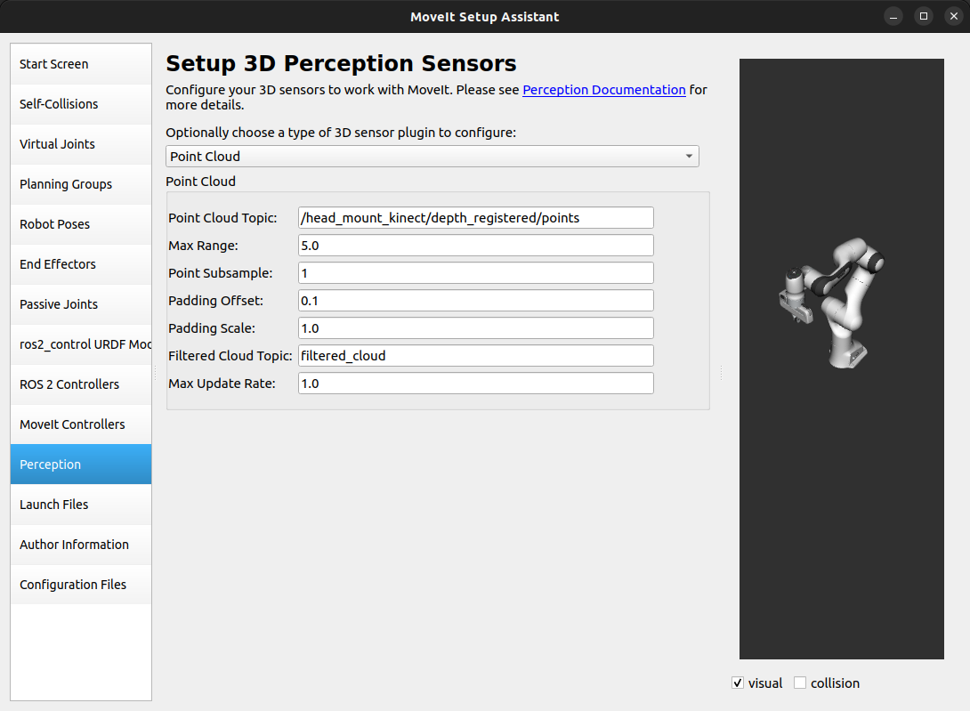
For more details about those parameters please refer to the Perception Pipeline tutorial.
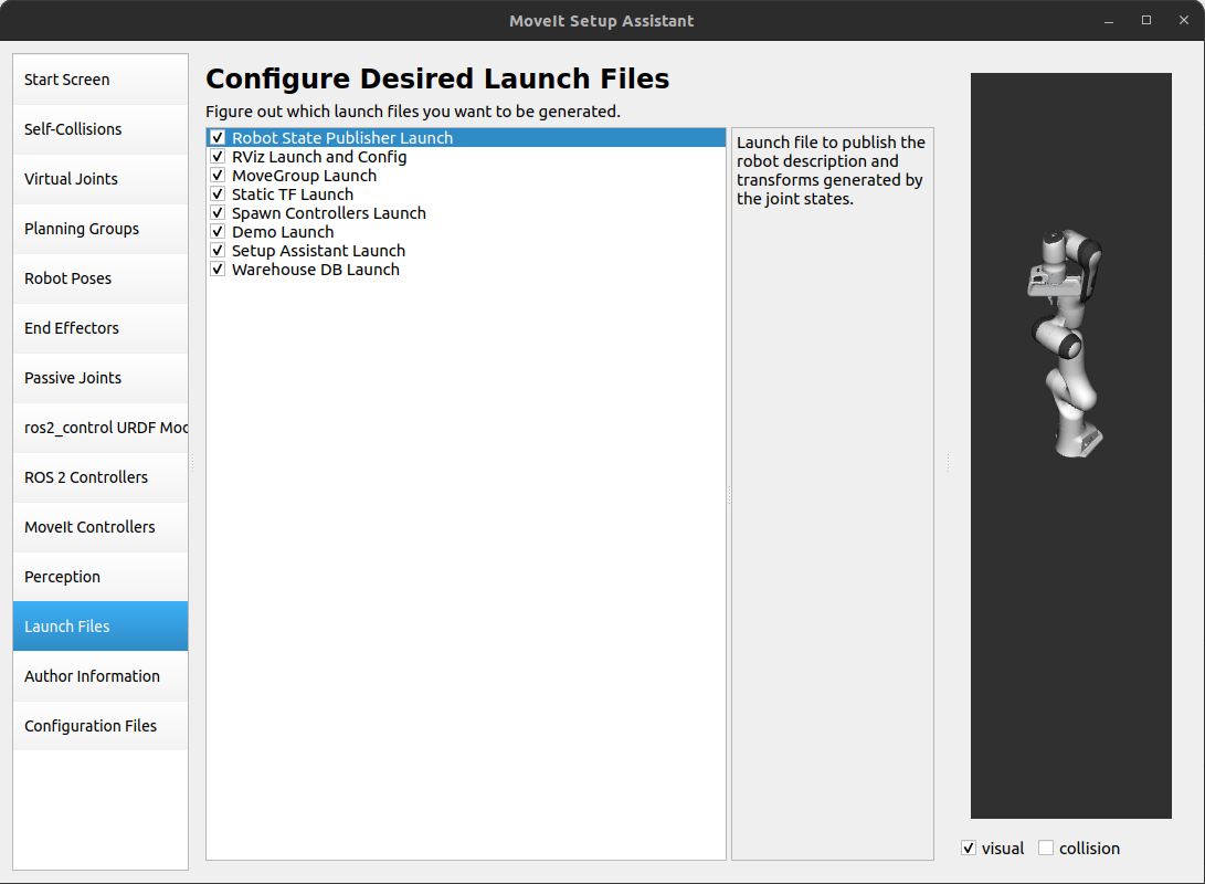
Step 12: Launch Files
In the Launch Files pane, you can view the list of launch files that will be generated. The default options are usually sufficient, but if you have specific requirements for your application, you can make changes as necessary. Click on each of the files to view a summary of their functionality.
Step 14: Generate Configuration Files
You are almost there. One last step - generating all the configuration files that you will need to start using MoveIt.
Click on the Configuration Files pane. Choose a location and name for the ROS 2 package that will be generated containing your new set of configuration files. Click Browse, select a good location (for example, your ROS 2 workspace’s src directory), click Create Folder, call it
panda_moveit_config, and click Open. All generated files will go directly into the directory you have chosen.Click on the Generate Package button. The Setup Assistant will now generate a set of launch and config files into the directory of your choice. All the generated files will appear in the files to be generated tab and you can click on each of them for a description of what they do. For more information on the generated files, see the Configuration section in the documentation.
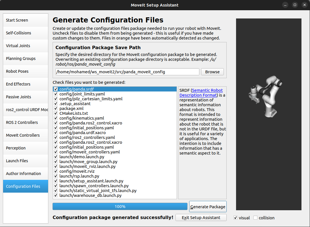
Congratulations! You are now done generating the configuration files you need for MoveIt.
Build the panda_moveit_config package and run the demo
To build only the generated panda_moveit_config package and run the demo, follow these steps.
cd ~/ws_moveit2
colcon build --packages-select panda_moveit_config
source install/setup.bash
Start the MoveIt demo to interactively plan and execute motions for the robot in RViz.
ros2 launch panda_moveit_config demo.launch.py
Check out this brief YouTube video for an example of how to
command the robot to move to the pre-defined ready pose and execute open and close motions on the hand.
What’s Next
Get Started with MoveIt Motion Planning using RViz
Learn how to use the generated configuration files to plan and visualize motion with MoveIt in RViz. Check out the MoveIt Quickstart in Rviz tutorial for a step-by-step guide.
Write Your First C++ MoveIt Application
Write your first C++ application using MoveIt with this tutorial, and familiarize yourself with the
MoveGroupInterfaceand use it to plan, execute, and visualize motion plans for your robot from this example.
URDF vs SRDF: Understand the Differences
See the URDF and SRDF page for more details on the components of the URDF and SRDF mentioned in this tutorial.
Explore available Inverse Kinematics Solvers